Description
 In the competitive landscape of British manufacturing, precision motion control is not an optional upgrade — it is the engineering foundation upon which productivity, repeatability, and machine longevity are built. Gear racks sit at the heart of this motion-control architecture, translating rotary torque from a pinion gear into controlled, repeatable linear displacement across CNC machining centres, laser cutting bridges, robotic linear tracks, gantry cranes, and automated warehousing systems. Whether you operate a precision engineering cell in Coventry, a sheet-metal fabrication shop in Sheffield, a food-processing line in County Durham, or a logistics fulfilment park outside Birmingham, choosing the correct gear rack specification can mean the difference between a machine delivering decade-long uptime and one plagued by backlash, tooth wear, servo alarms, and expensive unplanned downtime.
This guide draws on more than 18 years of hands-on application engineering across heavy industry, aerospace subcontract machining, and high-speed factory automation. It covers everything a UK procurement manager, machine-build engineer, or plant maintenance director needs to evaluate before specifying a gear rack system: operating principles, material grades and heat-treatment options, module and quality-level selection, long-travel assembly techniques, whole-life cost versus competing drive technologies, and how to work with a manufacturer who genuinely understands your application rather than simply quoting a catalogue part number. A real-world customer case study, independently verified performance data, and a detailed technical parameter table are included to help you make a justified, defensible procurement decision.
How Gear Racks Drive Modern Industrial Machinery
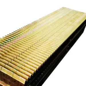
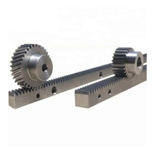
A gear rack is a straight, toothed bar that meshes with a rotating pinion gear to convert rotary motion into precise linear travel. The geometry appears simple, yet manufacturing a high-grade rack — one capable of maintaining sub-0.02 mm cumulative positioning accuracy across several metres of assembled length — demands CNC gear-grinding equipment calibrated against laser interferometry standards, controlled heat-treatment processes, and rigorous CMM inspection of every production batch. These are not commodity components; they are precision machine elements whose tooth geometry directly dictates positioning accuracy, vibration signature, service life, and the energy efficiency of the entire linear axis.
Tooth profile is one of the first engineering decisions in any gear rack application. Spur (straight-tooth) racks engage the pinion across the full tooth width simultaneously, producing a slight impulse at each tooth-mesh cycle. This is perfectly acceptable for moderate-speed, moderate-precision axes and has the advantage of easier assembly alignment. Helical gear racks, where the tooth is cut at an angle to the rack centreline (typically 14°–25°), provide progressive tooth engagement that dramatically reduces vibration, enables quieter high-speed operation, and increases the load-carrying capacity per unit of rack length. For this reason, servo-driven CNC axes, high-speed laser-cutting bridges, and robotic linear seventh-axis modules in UK automotive plants almost universally specify helical gear racks despite their slightly higher cost.
The module (m) — defined as the pitch circle diameter divided by tooth count — determines the coarseness of the tooth profile and, by extension, the load capacity per tooth. Low-module gear racks (m1–m2) are found in precision instruments, small CNC plasma tables, and compact linear actuators where forces are modest and positional resolution is paramount. Medium modules (m3–m6) cover the majority of CNC machining centres, router gantries, and handling robots. High modules (m8–m16) handle the enormous thrust loads in heavy-duty plasma cutting bridges, large CNC milling gantries, crane end-carriage drives, and construction equipment. Specifying an undersized module to reduce initial cost is one of the most common and expensive mistakes made by UK machine builders — the resulting premature tooth wear typically forces a full rack replacement within 12–18 months, at a total cost far exceeding the original saving.
Material Grades, Heat Treatment & Surface Options
 The material selected for a gear rack governs tooth hardness, contact-fatigue resistance, bending strength at the root, corrosion resistance, and machinability. Carbon steel C45 (equivalent to EN8 in British Standard) remains the workhorse grade for general industrial gear racks operating in dry or lubricated workshop conditions. It machines cleanly, has a well-characterised response to induction hardening, and yields a surface hardness of 48–54 HRC with a tough, ductile core — exactly the mechanical profile required by a high-cycle CNC axis that must resist both surface pitting and occasional impact loads from servo acceleration spikes.
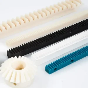
Where the operating environment involves continuous cutting fluid exposure, salt-spray in coastal UK locations, outdoor installation in agricultural or construction machinery, or high-pressure washdown in food-processing facilities, stainless steel gear racks — typically grade 316L — provide inherent corrosion immunity without surface coatings that can delaminate under cyclic load. For demanding high-speed, high-load duty cycles — common in UK aerospace component machining and automotive press-feed systems — alloy steel 42CrMo4 (equivalent to EN19T) is the correct specification. Through-hardened and then precision-ground, it delivers the combination of high core toughness and hard tooth flanks (54–58 HRC) that sustains accuracy over tens of millions of load cycles. Engineering polymer gear racks (acetal POM, nylon PA66) serve applications where metallic contamination is unacceptable or where a completely silent, self-lubricating drive is required — medical imaging gantries, laboratory automation, and light-duty pharmaceutical packaging lines being typical examples in the UK market.
Technical Parameter Reference Table
| Parameter | Standard Range | Heavy-Duty / Custom | Typical UK Application |
|---|---|---|---|
| Module (m) | m1 – m6 | m6 – m20 | CNC routers, heavy gantries, crane drives |
| Tooth Profile | 20° PA spur (straight) | Helical 14°–25°, custom PA | Servo axes, robotic 7th-axis tracks |
| Material | C45 carbon steel (EN8) | 42CrMo4 (EN19T), 316L SS, POM | Aerospace machining, food & pharma |
| Surface Hardness | 48–54 HRC (induction) | 54–62 HRC (carburised / nitrided) | High-cycle machining centres, press feeds |
| Bar Length | 500 mm – 3,000 mm | Up to 6,000 mm (custom ground) | Long-travel CNC gantries, ASRS cranes |
| Quality Grade (DIN) | DIN 9 – DIN 7 (hobbed) | DIN 6 – DIN 5 (precision ground) | Optical, semiconductor, defence |
| Pitch Deviation | ±0.05 mm / 300 mm | ±0.01 mm / 300 mm | AS9100 aerospace machining cells |
| Lubrication Method | Periodic grease / oil bath | Centralised auto-lube, sealed systems | 24/7 continuous production lines |
| Max. Traverse Speed | Up to 2 m/s (spur, DIN 7) | Up to 5+ m/s (helical, DIN 5 ground) | High-speed laser cutting bridges |
Key Application Scenarios for Gear Racks Across UK Industry
CNC Machining Centres
High-precision helical gear racks drive X and Y axes on vertical and horizontal machining centres across England’s Midlands manufacturing corridor. Sub-0.02 mm repeatability is essential for producing aerospace and automotive tooling to AS9100 and IATF 16949 standards, where any positioning error directly translates into a dimensional non-conformance on the finished component.
Laser & Plasma Cutting Bridges
Heavy-duty gear racks (m4–m8) mounted along bridge frames absorb the shock loads from rapid direction reversals and sustain the high traverse speeds — often exceeding 3 m/s — that modern fibre-laser systems demand to maintain cutting productivity on thick structural plate. UK steel fabrication shops in South Yorkshire and the North West depend on these racks running without interruption across long production campaigns.
ASRS & Automated Warehousing
Gear racks form the drive backbone of automated storage and retrieval (ASRS) stacker cranes in the UK’s rapidly expanding e-commerce fulfilment centres. Combining high-speed horizontal travel with precise vertical lift positioning, rack-and-pinion drives outperform cable and chain alternatives in both repeatability and service-life cost across multi-million-cycle annual duty cycles.
Robotic Linear Seventh-Axis Tracks
Collaborative robot (cobot) linear track systems rely on finely ground gear racks to extend robot reach beyond the fixed base envelope without sacrificing TCP positioning accuracy. This configuration is being adopted at pace by UK automotive Tier 1 suppliers transitioning from fixed-cell to flexible manufacturing, with the rack providing deterministic, feedback-correctable positioning across 6–12 m of linear travel.
Food Processing & Packaging Lines
316L stainless steel gear racks with electropolished body surfaces satisfy BRC Global Standard hygiene requirements in British bakeries, dairy lines, and confectionery plants. Chloride-resistant alloy selection and food-safe NLGI 2 grease lubrication allow full IP-rated washdown cycles without rack corrosion or lubricant contamination entering the product stream.
Stage Machinery & Architectural Systems
From dynamic stage-set fly systems in West End theatres to retractable roof mechanisms at UK sports stadia, gear rack and pinion drives provide the synchronised linear motion essential for large structural elements that must move precisely, quietly, and reversibly on tight production timescales — a performance profile that hydraulic and chain alternatives cannot match at scale.
Why UK Engineers Choose Gear Racks Over Competing Drive Technologies
Choosing a rack-and-pinion drive over a ball screw or linear motor is a systems engineering judgement that weighs travel length, peak speed, thrust force, duty cycle, and whole-life cost simultaneously. Gear racks win decisively in long-travel applications — typically beyond 1.5–2 metres — because they can be joined end-to-end without the critical-speed and whip limitations that constrain long ball screws. A 4-metre ball screw operating at high speed requires a large diameter to avoid resonance, adding rotational inertia that the servo motor must overcome at every direction reversal; a gear rack of the same travel length has no such constraint, and its mass does not rotate with the drive.
Compared with linear motors, rack-and-pinion drives retain a decisive cost-per-metre advantage across the axis lengths found in most British machine tools and handling systems, and they are far more tolerant of contamination from swarf, dust, and cutting fluid — a practical reality that any UK machine-shop engineer who has worked with linear motors in a machining environment will immediately appreciate. Maintenance transparency is another genuine advantage: tooth wear on a gear rack is fully visible during a scheduled inspection, whereas ball-screw preload loss and nut wear are invisible until positioning errors accumulate to the point of triggering servo alarms or producing out-of-tolerance parts.
✓ Unlimited Travel Length
Multiple gear rack bars joined end-to-end enable travel runs exceeding 30 m with no loss of positional integrity — ball screws cannot compete beyond 4–5 m.
✓ High-Speed Capability
Precision-ground helical gear racks support rapid traverse speeds beyond 5 m/s in servo-driven applications — well beyond ball-screw practical limits at long travel.
✓ Visible Wear & Simple PM
Tooth condition is inspectable without disassembly, enabling predictive maintenance scheduling and avoiding the hidden-failure mode that makes ball-screw degradation so costly.
✓ Lowest Installed Cost at Scale
Cost per metre of driven travel is substantially lower than linear motors, particularly for axes longer than 2 m — the standard configuration in most UK manufacturing gantry systems.
✓ Contamination Tolerance
Gear rack and pinion drives withstand swarf, coolant, and dust exposure that would destroy a linear-motor air gap — critical in British machining and fabrication environments.

Customer Success: Aerospace Machining Centre Re-Rack — Coventry, West Midlands
Client: A precision aerospace subcontractor based in Coventry, producing structural aluminium and titanium components for UK defence and commercial aviation programmes under AS9100 Rev D certification. The facility operates five-axis CNC machining centres on a two-shift, five-day production schedule.
Challenge: The existing DIN 7 spur gear racks on their largest gantry mill — a 12-metre X-axis — exhibited accelerated flank wear within 18 months of installation. The servo drive repeatedly reported following-error alarms at rapid traverse, disrupting production scheduling. An engineering investigation confirmed that the induction-hardened layer depth was insufficient for the imposed contact stress, and the spur tooth geometry was generating measurable vibration at 3 m/s that propagated into the spindle assembly, degrading titanium skin surface finish from Ra 0.8 µm specification to Ra 1.6–2.0 µm — triggering a downstream hand-polishing rework step on every batch.
Solution Specified: Helical gear rack assemblies, module 4, 19° helix angle, 42CrMo4 alloy steel through-hardened then precision-ground to DIN 5. The 12-metre X-axis was re-racked using four 3,000 mm bars with precision-machined joint faces, achieving cumulative pitch deviation below ±0.012 mm across the full 12-metre travel. Centralised automatic lubrication units were integrated at each rack section to maintain consistent oil-film thickness at all programmed traverse speeds.
Outcome: Following commissioning, measured vibration amplitude at 3 m/s traverse fell by 68%. Titanium skin surface finish recovered to Ra 0.76 µm without any modification to cutting parameters, eliminating the rework polishing step entirely. The site engineering manager calculated full payback of the gear rack replacement — including installation labour, machine downtime, and commissioning — within seven production weeks through scrap elimination and rework cost removal. Twenty-eight months post-installation, both rack assemblies show no measurable tooth wear and the machine passes all AS9100 process capability requirements at every quarterly audit.
What UK Engineers & Procurement Managers Say
We have tried three other gear rack suppliers over the past decade. None could match the pitch consistency on long assembly runs that this manufacturer delivers. Our gantry laser has run 24/7 for eight months without a single positioning alarm — unheard of with our previous setup.
James R.
Mechanical Engineering Director, Sheffield Sheet Metal Ltd, South Yorkshire
The custom stainless gear racks for our washdown conveyor line arrived with full CMM inspection reports and matched our drawings perfectly. Lead time was better than anything UK-based distributors quoted us. Genuinely impressive for a precision custom order.
Fiona T.
Procurement Manager, Northern Foods Processing Ltd, County Durham
After rebuilding our ASRS stacker crane with new gear racks, picking cycle time dropped 12% thanks to smoother acceleration profiles. The pre-sale engineering support and technical documentation were a level above anything we had received from other suppliers.
Mohammed A.
Head of Operations, West Midlands Logistics Distribution Park
Custom Gear Rack Manufacturing: Built to Your Exact Specification
Our factory operates a suite of CNC gear-grinding centres capable of producing gear racks from module 1 through module 20 in bar lengths up to 6,000 mm. The grinding process runs under in-process gauging with real-time feedback correction, achieving tooth-to-tooth pitch accuracy and involute profile tolerances that meet or exceed DIN 5 on every production run — not merely on qualification samples submitted once for approval. This batch-level consistency is what UK machine builders who cannot afford incoming inspection on every component need from a supplier they trust.
Our customisation capability extends far beyond choosing a module and material from a catalogue. We supply: custom cross-section profiles with integrated T-slots or bolt-pattern features; matched helical pinion gears designed and ground to pair with your rack; bespoke end-face machining for precision bolted joints when assembling multi-section long-travel axes; flame-hardening service for in-situ rehabilitation of large installed racks where removal is impractical; and complete rack-and-pinion sub-kit assemblies including matched bearings, mounting brackets, and automatic lubrication hardware. Every custom gear rack order is assigned a dedicated application engineer who reviews your load calculations, traverse speed, duty cycle, and environmental constraints before confirming the specification — so you have engineering justification for every parameter on your purchase order, not just a quote for something that looks about right.
Maintenance, Troubleshooting & Service-Life Extension

A well-specified, properly lubricated gear rack in a typical industrial application should deliver 20,000–40,000 hours of service before tooth-flank wear reaches the threshold requiring replacement. Achieving this service life depends on four factors that are consistently underestimated during commissioning: lubrication frequency and grease-film thickness at the tooth mesh point; pinion gear alignment to the rack face; back-pressure (anti-backlash) spring preload in the pinion carriage; and cleanliness of the engagement zone. In UK machining environments, swarf and coolant contamination of the rack teeth is the leading cause of premature wear — combining an auto-lubrication system with appropriate wipers or bellows guarding typically doubles the inspection interval compared with manually greased installations.
When following-error alarms or unusual vibration signatures appear on a gear rack-driven axis, the diagnostic sequence should begin with a visual inspection of tooth flank condition along the full travel length, paying particular attention to the sections that see the highest traverse frequency (typically in the middle one-third of the axis travel). Localised wear at specific positions usually indicates swarf accumulation or a lubrication dead zone rather than global rack deterioration, and is often addressable without replacement. Distributed uniform wear along the full travel is the expected end-of-life pattern and indicates a correctly functioning system that has simply reached its design fatigue life. Our technical team is available to review photographs of rack tooth condition and advise UK customers on whether reconditioning, partial replacement, or full re-racking is the most cost-effective course of action.
Serving British Industry: From Scotland to the South Coast
British manufacturing has always demanded components that are reliable, fully traceable, and built to specification rather than merely close enough. Whether you are commissioning a bespoke CNC machining cell in Coventry, upgrading an ASRS warehouse system in the East Midlands, building forestry or agricultural machinery in Lincolnshire, integrating robotic assembly at a Scottish defence subcontractor, or equipping a pharmaceutical production line in the Thames Valley, the gear racks driving your linear axes must perform without compromise across a working life measured in years — not months.
We have supplied gear racks to machine builders and end users across England, Scotland, Wales, and Northern Ireland, and we understand the specific environmental and regulatory challenges of operating in the United Kingdom. The salt-laden coastal air at manufacturing sites in Portsmouth, Teesside, and Aberdeen; the wide temperature swing in unheated fabrication sheds across northern England during winter; the IP69K washdown requirements of BRC-accredited food facilities from Glasgow to Bristol; the aerospace industry’s demand for CMM-traceable documentation on every motion-critical component — these are challenges we have addressed many times before, and our standard and custom gear rack ranges are specified with these conditions in mind. Stock is held for the most commonly requested module sizes and materials, and custom orders ship within agreed lead times, including documentation packages that satisfy the quality management requirements of ISO 9001, AS9100, and IATF 16949 certified UK facilities.
Frequently Asked Questions
Ready to Specify Your Gear Rack System?
Talk to an application engineer who has solved gear rack challenges across British aerospace, automotive, food, and logistics industries. Send your drawings, load data, or application description — we respond within one working day.
edit by gzl